How to process panoramic images for scene recognition?
The excerpt note is about panoramic images from Zhang et al., 2007.
Zhang, A. M. (2007). Robust appearance based visual route following in large scale outdoor environments. Proceedings of the Australasian Conference on Robotics and Automation, Brisbane, Australia, 2007.
Image Pre-processing
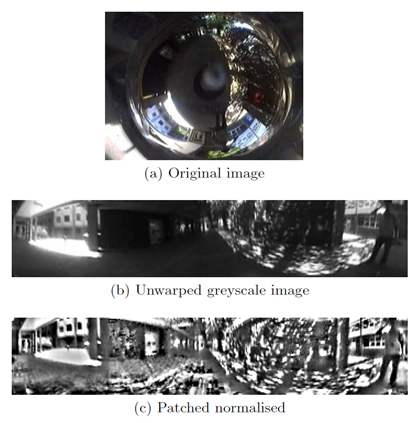
Identical image pre-processing steps are applied to both reference and measurement images. Input colour image is first converted into greyscale (colour information is unstable under changing lighting conditions) then “un-warped” (i.e. remapped) onto azimuth-elevation coordinates. An example of the original colour image and its unwarped greyscale image is shown in Figures 3a and 3b respectively, where horizontal axis is azimuth and vertical axis is elevation. Vertical field of view is restricted to [-50 deg, 20 deg].

Fig. 3: (a) Original colour image. (b) Converted to greyscale and mapped into azimuth-elevation coordinates, where the azimuth-axis is horizontal. (c) Patch normalised to remove lighting variations, using a neighbourhood of 17 by 17 pixels.
Patch normalisation is then applied to compensate for changes in lighting condition. It transforms the pixel values as follows:
 (1)
(1)
Where  and
and  are the original and normalised pixels respectively,
  and
and  are the mean and standard deviation of pixel values in a neighbourhood centred around
  . Figure 3c shows the result of applying patch normalisation to Figure 3b. A neighbourhood size of 17 by 17 pixels has worked well in the experiments.
Image Cross Correlation
The section addresses the problem of measuring an orientation difference between a measurement image and a reference image.
Orientation difference between reference and measurement image is therefore only a shift along the azimuth axis. This shift is recovered using Image Cross Correlation (ICC) performed efficiently in the Fourier domain. Let  denote azimuth and
  elevation. The frontal 180 degree field view of the reference image serves as the template, i.e.
  . Let the search range be
  such that the measurement image is limited to the angular range
  . Because only a 1D cross-correlation along the azimuth axis is performed, each row in the image is transformed into Fourier domain separately. Reference image is padded with zeros to the same size as the measurement image. If the measurement image is
  by
by  pixels, then the Fourier domain image consists of
  sets of 1D Fourier coefficients, each of a single row. Algorithmic complexity for a single image is
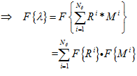
  . Convolution in spatial domain is equivalent to multiplication in Fourier domain:


 (2)
(2)
Where  is the Image Cross Correlation (ICC) coefficients,
  and
and  are the i th row in the reference and measurement image respectively, * is the convolution operator and
  is the Fourier transform operator. Equation 2 states that each corresponding row of the measurement and reference images are multiplied in Fourier domain. The results are then summed followed by an inverse Fourier transform to obtain the spatial domain cross-correlation coefficients. Complexity for the multiplication in Fourier domain is
  and for inverse Fourier transform is
  . Fourier transforms for the reference images are calculated offline after the teaching run and stored. The complexity of a complete ICC is thus
  where m is the number reference images to compare against. This is significantly better than the complexity of ICC performed in spatial domain which is
  . Comparing against 11 reference images only takes 2.3 ms on a 2.4GHz mobile Pentium 4 per measurement image.
For further more info, please read the Zhang 2007.
Zhang, A. M. (2007). Robust appearance based visual route following in large scale outdoor environments. Proceedings of the Australasian Conference on Robotics and Automation, Brisbane, Australia, 2007.
About
Brain Inspired Navigation Blog
New discovery worth spreading on brain-inspired navigation in neurorobotics and neuroscience
Recent Posts
- How locomotor development shapes hippocampal spatial coding?
- How human, animals, robots encode and recall place?
- How the brain constructs time and space and how these are related to episodic memory?
- How environmental novelty modulate rapid cortical plasticity during navigation?
- How the Hippocampal Cognitive Map Supports Flexible Navigation?
Tags
Categories
- 3D Movement
- 3D Navigation
- 3D Path Integration
- 3D Perception
- 3D SLAM
- 3D Spatial Representation
- AI Navigation
- Bio-Inspired Robotics
- Brain Inspired Localization
- Brain-Inspired Navigation
- Cognitive Map
- Cognitive Navigation
- Episodic Memory
- Excerpt Notes
- Flying Vehicle Navigation
- Goal Representation
- Insect Navigation
- Learning to Navigate
- Memory
- Neural Basis of Navigation
- Path Integration
- Path Planning
- Project
- Research Tips
- Robotic Vision
- Self-Flying Vehicles
- Semantic Memory
- Spatial Cognition
- Spatial Cognitive Computing
- Spatial Coordinate System
- Spatial Learning
- Spatial Memory
- Spatial Resoning
- Time
- Unclassified
- Visual Cortex
- Visual Cue Cells
Links
- Laboratory of Nachum Ulanovsky
- Jeffery Lab
- BatLab
- The NeuroBat Lab
- Taube Lab
- Laurens Group
- Romani Lab
- Moser Group
- O’Keefe Group
- DoellerLab
- MilfordRobotics Group
- The Space and Memory group
- Angelaki Lab
- Spatial Cognition Lab
- McNaughton Lab
- Conradt Group
- The Fiete Lab
- The Cacucci Lab
- The Burak Lab
- Knierim Lab
- Clark Spatial Navigation & Memory Lab
- Computational Memory Lab
- The Dombeck Lab
- Zugaro Lab
- Insect Robotics Group
- The Nagel Lab
- Basu Lab
- Spatial Perception and Memory lab
- The Neuroecology lab
- The Nagel Lab
- Neural Modeling and Interface Lab
- Memory and Navigation Circuits Group
- Neural Circuits and Memory Lab
- The lab of Arseny Finkelstein
- The Epstein Lab
- The Theoretical Neuroscience Lab
- Gu Lab (Spatial Navigation and Memory)
- Fisher Lab (Neural Circuits for Navigation)
- The Alexander Lab (Spatial Cognition and Memory)
- Harvey Lab (Neural Circuits for Navigation)
- Buzsáki Lab
- Brain Computation & Behavior Lab
- ……